Seismic-Resistant Design: Principles and Advanced Techniques for Earthquake-Safe Structures
A Comprehensive Engineering Guide to Protecting Buildings Against Seismic Forces
1Understanding Seismic Forces: The Physics of Earthquake Loading
Before designing earthquake-resistant structures, engineers must understand the nature of seismic forces. Unlike static loads (gravity, occupancy), seismic loads are dynamic, cyclical, and unpredictable in magnitude and direction.
Ground Motion Characteristics:
Earthquakes generate three types of seismic waves:
- **P-waves (Primary)**: Compressional waves that arrive first, causing vertical ground motion
- **S-waves (Secondary)**: Shear waves that cause horizontal motion, typically more damaging
- **Surface waves**: Rayleigh and Love waves that cause rolling and lateral motion
Key Parameters:
- Peak Ground Acceleration (PGA) Maximum acceleration experienced at ground level, expressed as fraction of gravity (g):
- **Spectral Acceleration (Sa)**: Acceleration experienced by structures of specific natural periods
- **Duration**: Longer earthquakes cause more cumulative damage through repeated cycling
- **Frequency Content**: Buildings resonate when ground motion frequency matches their natural frequency
Response Spectrum Analysis:
The response spectrum is fundamental to seismic design. It plots maximum acceleration response against structural period:
Sa(T) = SDS for T < T0 Sa(T) = SD1/T for T > TS
Where:
- SDS = Short-period design acceleration
- SD1 = 1-second period design acceleration
- T = Structural natural period
Practical Implication:
Stiff, low-rise buildings (short period) experience higher accelerations but smaller displacements. Flexible, tall buildings (long period) experience lower accelerations but larger displacements. This relationship fundamentally influences design strategy.
2Seismic Design Philosophy: Life Safety vs. Performance-Based Design
Modern seismic design operates under two complementary philosophies: prescriptive code-based design and performance-based earthquake engineering (PBEE).
Traditional Code-Based Approach:
Building codes establish minimum requirements based on:
- **Seismic Design Category (SDC)**: A through F, based on ground motion intensity and building risk category
- **Risk Category**: I through IV, based on occupancy and consequence of failure
- **Response Modification Factor (R)**: Accounts for structural ductility and energy dissipation capacity
Design Base Shear:
V = Cs × W
Where Cs = SDS / (R/Ie) but not exceeding SD1 / (T × R/Ie)
Performance-Based Earthquake Engineering (PBEE):
PBEE defines explicit performance objectives for different earthquake intensities:
| Earthquake Level | Return Period | Performance Objective | |-----------------|---------------|----------------------| | Frequent (FOE) | 43 years | Immediate Occupancy | | Design (DBE) | 475 years | Life Safety | | Maximum (MCE) | 2,475 years | Collapse Prevention |
Performance Levels Defined:
- Operational Building fully functional, minimal damage:
- **Immediate Occupancy (IO)**: Minor damage, building safe to occupy
- **Life Safety (LS)**: Significant damage, but structural integrity maintained
- **Collapse Prevention (CP)**: Extensive damage, building on verge of collapse but standing
Why PBEE Matters:
Traditional codes focus on life safety in rare events but may result in economically devastating damage in more frequent earthquakes. PBEE allows owners and designers to make informed decisions about acceptable risk levels and investment in seismic protection.
3Lateral Force-Resisting Systems: Structural Configurations
The lateral force-resisting system (LFRS) is the structural backbone that transfers seismic forces from the building mass to the foundation. Selection of the appropriate LFRS depends on building height, geometry, architecture, and seismic hazard.
Moment-Resisting Frames (MRF):
Moment frames resist lateral forces through rigid beam-column connections that develop bending moments.
*Advantages*:
- Architectural flexibility (no diagonal braces or walls)
- Large open floor plans possible
- Ductile behavior when properly detailed
*Disadvantages*:
- More flexible, larger drifts
- Connection details are critical and expensive
- Limited to moderate heights without becoming uneconomical
R-factors:
Special MRF (R=8), Intermediate MRF (R=5), Ordinary MRF (R=3.5)
Braced Frames:
Braced frames use diagonal members to form vertical trusses that resist lateral forces through axial action.
*Types*:
- **Concentrically Braced Frames (CBF)**: Diagonals meet at beam-column joints
- **Eccentrically Braced Frames (EBF)**: Diagonals offset to create link beams that yield and dissipate energy
- **Buckling-Restrained Braced Frames (BRBF)**: Special braces that yield in both tension and compression
R-factors:
Special CBF (R=6), EBF (R=8), BRBF (R=8)
Shear Walls:
Shear walls are vertical planar elements that resist lateral forces through in-plane shear and bending.
*Materials*:
- Reinforced concrete (most common)
- Reinforced masonry
- Steel plate shear walls
- Cross-laminated timber (CLT)
R-factors:
Special RC walls (R=5-6), Ordinary walls (R=4)
Dual Systems:
Dual systems combine moment frames with shear walls or braced frames. The moment frame must resist at least 25% of the design seismic force. This redundancy provides superior performance.
R-factors:
Dual systems with special MRF (R=7-8)
4Ductility and Energy Dissipation: The Key to Seismic Survival
Ductility is the ability of a structure to undergo large inelastic deformations without losing strength. In seismic design, ductility is not just desirable; it is essential for survival.
Why Ductility Matters:
Designing structures to remain elastic during major earthquakes would require enormous member sizes and would be economically impractical. Instead, we design structures to yield in a controlled manner, dissipating seismic energy through inelastic deformation.
Ductility Demand and Capacity:
μ = Δmax / Δyield
Where:
- μ = Displacement ductility ratio
- Δmax = Maximum displacement
- Δyield = Yield displacement
Typical ductility demands:
- Low seismicity zones: μ = 1.5-2.0 - Moderate seismicity: μ = 3.0-4.0 - High seismicity: μ = 5.0-8.0
Capacity Design Principle:
Capacity design ensures that inelastic action occurs in designated elements (ductile links) while protecting other elements from yielding.
Example: Strong Column-Weak Beam:
ΣMnc ≥ 1.2 × ΣMnb
Column moment capacity must exceed beam capacity by 20% to prevent story collapse mechanisms.
Plastic Hinge Zones:
In moment frames, plastic hinges should form in beams near connections, not in columns. Special detailing requirements include:
- Close spacing of transverse reinforcement
- Adequate development of longitudinal bars
- Confinement of concrete core
Energy Dissipation Mechanisms:
- Hysteretic damping Energy dissipated through material yielding:
- **Viscous damping**: Inherent damping from material properties (typically 2-5% critical)
- **Added damping**: Supplemental devices (dampers, isolators)
Detailing for Ductility (RC Structures):
- Maximum spacing of ties in plastic hinge zones d/4 or 6db or 150mm:
- Minimum confinement reinforcement ratio: ρs ≥ 0.12 fc'/fyt
- Adequate lap splice lengths outside plastic hinge regions
5Base Isolation: Decoupling Buildings from Ground Motion
Base isolation is one of the most effective seismic protection strategies, fundamentally changing how structures respond to earthquakes by decoupling the building from ground motion.
Principle of Base Isolation:
Isolators are placed between the foundation and superstructure, creating a flexible layer that:
- Lengthens the building's natural period (typically to 2-4 seconds)
- Reduces spectral acceleration experienced by the structure
- Concentrates displacement at the isolation level
Period Shift Effect:
For a non-isolated building with T = 0.5s experiencing Sa = 1.0g: With isolation extending period to T = 3.0s, Sa reduces to approximately 0.15g
Types of Isolation Devices:
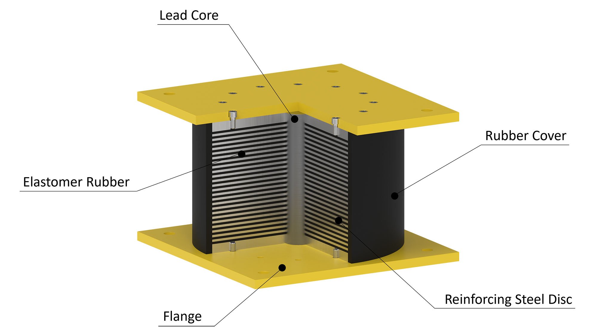
Lead-Rubber Bearings (LRB):
- Laminated rubber with steel shims - Central lead core provides energy dissipation - Self-centering capability - Typical effective damping: 15-30%
Friction Pendulum Bearings (FPB):
- Curved sliding surface creates pendulum motion - Period depends on radius of curvature: T = 2π√(R/g) - Excellent for heavy structures - Velocity-dependent friction provides damping
High-Damping Rubber Bearings (HDRB):
- Modified rubber compounds with inherent damping - No lead core required - Effective damping: 10-20%
Design Considerations:
- Displacement capacity Isolators must accommodate MCE displacements (often 300-600mm):
- **Vertical load capacity**: Must support full gravity loads plus vertical seismic
- **Moat gap**: Clearance around building perimeter
- **Flexible connections**: Utilities must span isolation gap
Ideal Applications:
- Hospitals and emergency facilities:
- Data centers and critical infrastructure
- Museums and historic structures
- Buildings with sensitive equipment
Limitations:
- Higher initial cost (typically 3-5% of structural cost):
- Not suitable for very tall, flexible buildings
- Requires maintenance access to isolators
- Soft soil conditions may reduce effectiveness
6Energy Dissipation Devices: Passive Damping Systems
Passive energy dissipation devices (dampers) absorb seismic energy, reducing structural response without external power. These systems have become increasingly common in high-performance seismic design.
Viscous Fluid Dampers:
These devices force fluid through orifices, converting kinetic energy to heat.
*Force-velocity relationship:* F = C × V^α
Where:
- C = Damping coefficient
- V = Velocity
- α = Velocity exponent (typically 0.3-1.0)
*Advantages*:
- Velocity-dependent force (out of phase with displacement)
- No added stiffness at low velocities
- Effective across wide frequency range
- Maintenance-free design life of 25+ years
Metallic Yield Dampers:
These devices dissipate energy through yielding of steel elements.
*Types*:
- **ADAS (Added Damping and Stiffness)**: X-shaped steel plates
- **TADAS (Triangular ADAS)**: Triangular steel plates for uniform yielding
- **BRBs (Buckling-Restrained Braces)**: Steel core in concrete-filled tube
*Advantages*:
- Highly reliable, simple mechanism
- Large energy dissipation capacity
- Relatively low cost
*Disadvantages*:
- May require replacement after major earthquake
- Adds stiffness to structure
Friction Dampers:
These devices dissipate energy through controlled friction between sliding surfaces.
*Characteristics*:
- Rectangular hysteresis loop
- Activation threshold (slip force)
- Temperature-independent response
Viscoelastic Dampers:
Polymer materials shear between steel plates, providing both stiffness and damping.
*Applications*:
- Wind-induced vibration control
- Combined wind and seismic applications
- Retrofit of existing buildings
Design Approach:
Added damping reduces response according to: R_damped = R_undamped × B
Where B = damping coefficient reduction factor:
- 5% damping: B = 1.0
- 10% damping: B = 0.83
- 20% damping: B = 0.67
- 30% damping: B = 0.56
7Structural Irregularities: Avoiding Seismic Vulnerabilities
Structural irregularities create stress concentrations and unpredictable behavior during earthquakes. Building codes penalize irregular structures with more stringent design requirements or outright prohibitions.
Horizontal (Plan) Irregularities:
1. Torsional Irregularity:
Occurs when the center of mass and center of rigidity are significantly offset, causing the building to twist during earthquakes.
*Criterion:* Δmax/Δavg > 1.2 (irregularity exists) *Criterion:* Δmax/Δavg > 1.4 (extreme irregularity)
*Solutions*:
- Distribute lateral elements symmetrically
- Increase stiffness at flexible edges
- Add dampers to reduce torsional response
2. Re-entrant Corners:
L-shaped, T-shaped, or U-shaped plans create stress concentrations at inside corners.
*Criterion:* Projection > 15% of plan dimension
*Solutions*:
- Seismic joints to separate wings
- Strengthen re-entrant corners
- Provide collectors along re-entrant edges
3. Diaphragm Discontinuity:
Large openings or abrupt changes in floor stiffness disrupt force transfer.
*Criterion:* Opening > 50% of gross floor area
Vertical Irregularities:
1. Soft Story:
Occurs when a story is significantly more flexible than stories above, concentrating deformation.
*Criterion:* Stiffness < 70% of story above or < 80% of average of three stories above
*Historical failures:* First-floor retail with open fronts, parking podiums
*Solutions*:
- Add bracing or walls at soft story
- Use moment frames to maintain stiffness
- Base isolation (transforms soft story into asset)
2. Weak Story:
Occurs when a story has significantly less strength than stories above.
*Criterion:* Strength < 80% of story above
3. Weight (Mass) Irregularity:
*Criterion:* Mass > 150% of adjacent story
4. Vertical Geometric Irregularity:
*Criterion:* Dimension > 130% of adjacent story
Design Implications:
Irregular structures in SDC D, E, or F may require:
- Nonlinear dynamic analysis
- Higher redundancy factors
- More stringent drift limits
- In extreme cases, certain systems prohibited
8Foundation and Soil-Structure Interaction
The foundation system and underlying soil significantly influence seismic response. Poor foundation design or inadequate soil consideration has caused numerous building failures.
Site Classification:
Building codes classify sites based on soil properties:
| Site Class | Description | Vs30 (m/s) | |-----------|-------------|------------| | A | Hard rock | > 1500 | | B | Rock | 760-1500 | | C | Dense soil/soft rock | 360-760 | | D | Stiff soil | 180-360 | | E | Soft soil | < 180 | | F | Special study required | - |
*Vs30 = Average shear wave velocity in top 30m*
Site Amplification:
Soft soils amplify ground motion, particularly at longer periods. Site coefficients Fa and Fv modify design accelerations:
SMS = Fa × SS (short period) SM1 = Fv × S1 (1-second period)
Soil-Structure Interaction (SSI):
SSI effects can be beneficial or detrimental:
*Period Lengthening:* Flexible soil increases effective period, potentially reducing forces *Foundation Damping:* Energy radiates into soil, adding effective damping *Base Rocking:* Foundation rotation adds displacement demand
Foundation Types for Seismic Zones:
Mat (Raft) Foundations:
- Distribute loads over large area - Resist overturning effectively - Good for soft soils
Deep Foundations (Piles/Drilled Shafts):
- Transfer loads to competent bearing stratum - Must consider kinematic interaction (soil deformation imposes forces on piles) - Liquefaction potential requires special consideration
Liquefaction Considerations:
Liquefaction occurs when saturated loose sand loses strength during shaking.
*Assessment factors*:
- Groundwater level
- Soil gradation and density
- Earthquake magnitude and duration
*Mitigation strategies*:
- Ground improvement (stone columns, compaction)
- Deep foundations through liquefiable layer
- Structural design for post-liquefaction settlement
Foundation Ties:
Individual footings must be tied together to prevent relative movement:
Tie force: F = 0.1 × SDS × P
Where P = larger column load supported by tied footings
9Seismic Retrofit Strategies for Existing Buildings
Millions of buildings worldwide were constructed before modern seismic codes or in areas where seismic hazard was underestimated. Retrofit strategies must balance seismic improvement with practical and economic constraints.
Assessment of Existing Buildings:
Tier 1 (Screening):
- Checklist-based evaluation - Identifies obvious deficiencies - Quick and low-cost
Tier 2 (Deficiency-Based):
- Quantitative evaluation of deficiencies identified in Tier 1 - Linear analysis methods - Determines if retrofit is needed
Tier 3 (Systematic):
- Comprehensive building evaluation - Nonlinear analysis often required - Determines performance level achievable
Common Deficiencies:
- Inadequate lateral force-resisting system:
- Non-ductile concrete details (lack of confinement)
- Soft/weak story configurations
- Unreinforced masonry
- Poor connections (precast concrete, wood diaphragms)
- Inadequate foundation anchorage
Retrofit Approaches:
1. System Strengthening:
- Add new shear walls or braced frames - Steel moment frames at perimeter - New foundation elements
2. Stiffness Modification:
- Add bracing to reduce drift - Remove or stiffen soft stories
3. Ductility Enhancement:
- Concrete column jacketing (steel or FRP) - Beam-column joint strengthening - Replace non-ductile coupling beams
4. Load Path Completion:
- Add collectors and drag struts - Strengthen diaphragm connections - Improve foundation ties
5. Seismic Isolation Retrofit:
- Install isolators beneath existing columns - Highly effective but requires temporary shoring - Ideal for historic buildings
6. Supplemental Damping:
- Add viscous or metallic dampers - Reduces forces without major structural work - Can be architecturally unobtrusive
Performance Objectives for Retrofit:
ASCE 41 defines retrofit objectives:
- **Basic Safety**: Life Safety at BSE-1, Collapse Prevention at BSE-2
- **Enhanced**: Better than Basic Safety
- **Limited**: Less than Basic Safety (may be acceptable for lower risk)
10Case Studies: Lessons from Real Earthquakes
Historical earthquakes provide invaluable lessons that have shaped modern seismic design practice.
1994 Northridge Earthquake (M6.7, California):
*Key Failures*:
- Welded steel moment frame connections fractured
- Parking structure collapses (inadequate connections)
- Non-ductile concrete frame failures
*Lessons Learned*:
- Led to complete revision of steel connection design
- Development of reduced beam section (RBS) connections
- Recognition that code-compliant buildings can still fail
1995 Kobe Earthquake (M6.9, Japan):
*Key Failures*:
- Elevated highway collapse (non-ductile columns)
- Soft-story building collapses
- Port infrastructure destroyed
*Lessons Learned*:
- Japan strengthened retrofit requirements
- Advanced base isolation research accelerated
- Performance-based design gained acceptance
2010 Chile Earthquake (M8.8):
*Key Observations*:
- Modern buildings performed well overall
- Some RC wall buildings experienced compression failures
- Hospital and critical facility damage extensive
*Lessons Learned*:
- Importance of confinement at wall boundaries
- Need for functional recovery, not just life safety
- Value of redundancy in lateral systems
2011 Christchurch Earthquake (M6.3, New Zealand):
*Key Failures*:
- Unreinforced masonry building collapses
- CTV building collapse (115 deaths), non-ductile concrete
- Extensive liquefaction damage
*Lessons Learned*:
- Proximity to fault matters more than magnitude alone
- Importance of soil investigation
- Need for resilience-based design
2016 Kumamoto Earthquake Sequence (M7.0, Japan):
*Key Observations*:
- Traditional wooden houses outperformed older concrete
- Base-isolated hospital remained functional
- Repeated shaking caused cumulative damage
*Design Implications*:
- Consider earthquake sequences in design
- Importance of inspectable, repairable systems
- Base isolation effectiveness confirmed
Statistical Summary from Recent Earthquakes:
| Building Type | Collapse Rate | Heavy Damage Rate | |--------------|---------------|------------------| | Pre-1970 URM | 5-10% | 20-30% | | Pre-1970 RC | 1-3% | 10-20% | | Post-1990 RC | < 0.1% | 2-5% | | Base-isolated | 0% | < 1% |
Conclusion
Seismic-resistant design represents the intersection of physics, materials science, and engineering judgment. The principles outlined in this guide, from understanding ground motion characteristics to implementing advanced protection systems, form the foundation of earthquake-safe construction. Modern seismic engineering has achieved remarkable successes. Buildings designed to current codes rarely collapse, even in severe earthquakes. However, the profession continues to evolve. Performance-based design offers more transparent risk communication. Advanced materials enable lighter, more efficient structures. Computational tools allow optimization of complex systems. And lessons from each earthquake refine our understanding and improve our practice. Yet challenges remain. Millions of existing buildings predate modern codes and require assessment and retrofit. Climate change may alter seismic hazards through reservoir-induced seismicity and permafrost degradation. And the ultimate goal has shifted from mere survival to rapid recovery, demanding structures that not only protect lives but also restore communities. For structural engineers, seismic design is both a profound responsibility and an opportunity for meaningful impact. Every building we design that survives an earthquake represents lives saved and communities preserved. This is the essence of our profession. **At CW Structura Intelligence, we combine advanced seismic analysis with practical design experience to create structures that protect people and investments. Our expertise spans new construction, retrofit evaluation, and performance-based design for critical facilities across all seismic zones.**
Ready to ensure your project meets the highest seismic safety standards? Contact CW Structura Intelligence for expert consultation on earthquake-resistant design.
Contact UsAbout the Author

Lens Wolph Kenley Ciceron
Lens Wolph Kenley Ciceron is the founder of CW Structura Intelligence, bringing expertise in structural engineering, construction strategy, and AI-driven innovation to the global engineering community.